Rubix iO: Modbus RS485 Wiring
Nube-iO Rubix IO Modules are a pure Modbus device; All communications with the IO Modules are via Modbus. This article will detail the correct wiring for the Modbus RS485 Network. To communicate via Modbus the Rubix IO Module must also have its Onboard DIP Switches configured correctly to set the Modbus Serial Communication Parameters.
Preparation
- Rubix IO Modules: Configuring Modbus Communications Parameters
Connecting RS485 Network (Wired Network)
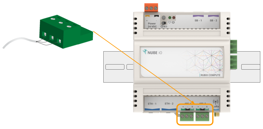
When using the wired network connection, the IO Module RS485 Modbus connection is used. The connector is terminated and installed as shown below.
When Networking multiple IO Modules on an RS485 network, each controller is connected in a `Daisy Chain`. Controllers that are connected between 2 other controllers will have 2 wires (one from the previous controller and one from the next controller) in the same terminal. Ensure A/+ and B/- wires are kept consistent for all controllers on the network.
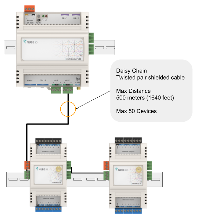
 Note: Modbus settings on the gateway controller must match those set on the connected IO Modules. All devices on a Modbus network must have the same Modbus network settings.
Modbus RS485 Passthrough - Wireless Modbus Extender
Modbus RS485 Passthrough is available on IO Modules equipped with a LoRa (Wireless) Comms. In this mode the wired Modbus RS485 data is sent wirelessly to the LoRa gateway.
When using a Rubix IO Module as a wireless Modbus passthrough, the RS485 network is connected only to the third party device and the Rubix IO Module, as shown below. The RS485 wiring is the same as described above.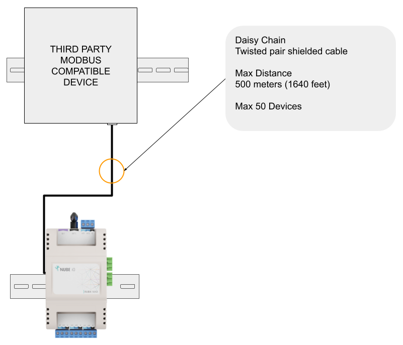
RS485 Network Wiring
When wiring an RS485 network a single shielded twisted pair (STP) cable should be used. The twisted pair cable cancels out interference and ensures that the 2 conductors are at the same lengths. Having a ground shield on the twisted pair cable further provides protection to interference on the RS485 network.