Rubix Platform: Overview
Introduction To Rubix Platform
Rubix Platform is the browser based user interface for many of the Nube-iO services. Rubix Platform is the main management tool for configuring Local/Remote Device Settings, Sensor Gateway Connectivity, Data Management, System Monitoring, and Application Management.
Platform Configuration
Rubix Platform is a browser-based user interface. It can be accessed on any supported web browser (Chrome, Firefox, Safari, Internet Explorer, ...) by entering the IP Address, and Port Number [1414] in the browser's URL address bar.
To open Rubix Platform first type in the IP address where Rubix Platform is running: this could be on a controller, a PC, or a web server. Next type a Colon [ : ]. Finally type the Port Number; the default port number for Rubix Platform is 1414. The URL Address should take the following form <IP Address>:<Port Number>
For example: 192.168.15.10:1414
Note: The IP Address or Port Number may be different if Rubix Platform is being accessed through a router or networking service with port forwarding enabled.
If the device's IP address is unknown try the following:
- If you are accessing Rubix Platform on a Nube-iO Rubix Compute controller try IP Address 192.168.15.10 with the ETH-2 ethernet port connected to your PC. OR connect the ETH-1 ethernet port to your router and check your router DHCP devices for the IP Address. For further information see Connecting to a Rubix Compute.
- Try to use an IP scanning tool such as Advanced IP Scanner or Angry IP Scanner to find the device's IP address.
- Contact a network administrator to check the networking details for the device running Rubix Platform.
Login with User Credentials
Once you have navigated to Rubix Platform, if you have not signed-in recently, a login screen will appear, prompting for a username and password.
Note: If the username and password have not been changed, they will be the default values. The default username is admin and the default password is N00BWires(note there are 2 Zeros in N00B).
After successful login you will see the Rubix Platform user interface. To find out what to do next, please see Navigating Rubix Platform or Getting Started Guide: Rubix Platform for more information.Updating Rubix Platform Login Credentials
The password for accessing Rubix Platform can be changed from the default values.At the current time, only the login password can be modified. The login username ('admin') is constant.
Updating Login Password
- Navigate to `Update Password` Menu: Select 'Update Password' from within the Sidebar
Button; This will show the Update Password popup.
- Enter the Current Password: Enter the current login password. If the login credentials are still default it will be `N00BWires` (Note: there are 2 Zeros in N00B).
- Enter the New Password: Enter your new login password twice. New passwords must match to be saved.
- Save New Password: Clicking `SAVE` will update the login credentials.
Note: If login credentials have not been previously updated, use default credentials. The default username is admin and the default passwor d is N00BWires (Note: there are 2 Zeros in N00B).
Setting System Time of Rubix Platform
The Rubix Platform can be set to the local time zone of the location the devices are in, as this allows accurate reporting data and management of devices without time mismanagement.Rubix Platform time setting is set by selecting a timezone. There are 2 types of timezone settings in Rubix Platform, it is important to understand the differences as they have different functions.
Valid Timezones
Timezones in Rubix Platform are selected from the TZ Database, which supports all of the global timezones, as well as secondary timezones to handle any timezone specifics properties such as daylight savings time. Each timezone has an identifier like `Australia/Sydney`. See the List of TZ Database Timezones for all valid timezones in the TZ Database.
Platform Display Timezone vs Host Device Timezone
There are 2 types of timezone settings in Rubix Platform, it is important to understand the differences as they have different functions.
- Host Device Timezone - This is the timezone that the host device (the one running Rubix Platform) is set to. This timezone will be used for all host device functions that reference the time. Changing this timezone may have effects on other processes running on the host device.
- Platform Display Timezone - This is the timezone that the timestamps in Rubix Platform are displayed in. This timezone can be different from the Host Device Timezone. This timezone setting is specific to the user viewing the Rubix Platform instance, not to the host device itself.
For Example: A Host Device Timezone is set to Australia/Sydney (AEST) and a sensor reading timestamp is at 6:00 am. If the Platform Display Timezone is also set to Australia/Sydney, then the timestamp displayed in Rubix Platform will be 6:00am. However, if the Platform Display Timezone is set to Australia/Perth, then the same sensor reading timestamp will be displayed as 3:00am; as this is the equivalent time for the user reading in Australia/Perth.
Changing Timezones
Host Device TimezoneTo set the Host Device Timezone: Select 'Apps > Services' from the Rubix Platform Sidebar; Next select the 'HOST INFO' Tab; In the 'SYSTEM TIME' tile the Host Device Timezone can be selected from the Timezones dropdown menu. Hint: Once the dropdown is open, you can start to type the timezone to filter the results. Once you select the Timezone (from the dropdown) Rubix Platform will ask you to confirm the change.Above the Timezone dropdown there are several text fields that show the current time in UTC and Local time. Other timezone abbreviations for the selected timezone are also shown.Platform Display TimezoneTo set the Platform Timezone: Select 'Settings' from the Rubix Platform Sidebar; Next select the 'SETTINGS' Tab; In the 'Timezone' tile the Platform Display Timezone can be selected from the Timezones dropdown menu. Hint: Once the dropdown is open, you can start to type the timezone to filter the results. Once you select the Timezone (from the dropdown) , a green alert will appear stating 'success' if the timezone has been successfully changed. The Rubix Platform page in the browser should be refreshed after the timezone change has been made.
Customising the Rubix Platform Sidebar
The Rubix Platform user interface uses a Sidebar for navigation of the platform. This sidebar can be customised with desired links to sections relevant to use case.
Selecting Menu Items to Appear in the Sidebar
At the bottom of the Sidebar, click on the `Settings` button. Select the `SIDEBAR SETTING` tab. On this page is there are two tiles: Rubix tile and Rubix Flow tile.Within these tiles there are check boxes that correspond to the elements available for display in the Sidebar. A ticked check box means the current item will be displayed. Check or uncheck the check box to the item you'd like displayed or hidden. It should be noted that to enable selection of items in the Rubix Flow tile, the toggle switch next to Rubix Flow should be switched on.Importing and Exporting Sidebar settings
The Sidebar settings can be exported and imported for easier configuration on multiple devices which share the same Sidebar configuration. The way the Sidebar settings are imported and exported is by using a string of XML text.Exporting Sidebar settingsTo export the current Sidebar settings, click the `Export` button in the top left of the page, this will open a pop-up in which contains the raw XML formatted data of the current Sidebar settings. Copy this text and save in a text file for future use.Importing Sidebar settingsTo import Sidebar settings, click the `Import` button in the top left of the page, this will open a pop-up in which contains a section where the required Sidebar settings XML text can be pasted. Click `Save` to import the Sidebar settings.
Navigation of Rubix Platform
Rubix Platform is designed to be user friendly and intuitive, there
are a few important features and naming conventions that you should
become familiar with so that more advanced articles will be easier to
follow.
There are 2 main areas of the Rubix Platform User Interface, the Sidebar, and the Main Panel. Each of these areas contains various elements; the common ones are described below.
Sidebar
The Sidebar is the main method of navigating through Rubix Platform. It is located on the left hand side of the page, and can be expanded or collapsed. The Sidebar contains links to all of the available pages.
- Title, Expand/Collapse, and Lock - At the top of the Sidebar we find 'Rubix Platform' and below that the name of the Client (as configured in Device Info). The Sidebar can be collapsed by using the left arrow button on the top right of the Sidebar, and by clicking anywhere on the collapsed Sidebar to expand again. The Lock button, when activated (blue) will lock the Sidebar in the expanded position.
- Apps and Tools Links - In the middle of the Sidebar we find links to the Apps and Tools that are available. The options shown can be modified to display only the relevant Apps and Tools: See Customising the Sidebar for details.
- Current Device - At the bottom of the Sidebar, the Site Name and Device Name are shown. Below these there is a
- User and Version - Displays the currently signed in user, and the current version of Rubix Service.
- Upgrade Rubix - Access the Update Rubix Service wizard: See Updating Rubix Service.
- Device Info - Access the Device Info configuration page: See Configuring Device Info.
- Master/Slave Configuration - Access the Master/Slave configuration page: See Configuring Master/Slave.
- Token Update - Access the Token configuration page: See Configuring Rubix Token.
- Configure Endpoints - Access the Endpoint configuration page: See Configuring Endpoints.
- Update Password - Access the Update Password configuration page: See Updating Login Password.
- Logout - Logout of the current Rubix Platform session: See Rubix Platform: Access and Login.
Main Panel
The Main Panel of Rubix Platform is where majority of the configuration and actions occur. The Main Panels contains many elements that are specific to the type of App/Tool selected on the Sidebar. Below are a few of the common elements that will help a user navigate the Main Panel for many of the common App/Tool pages.
Title of Current Page
The Title of the Current Page is displayed on the top left of the Main Panel.
Tabs
Tabs are located at the top right of the Main Panel. Tabs can be considered subsections of the App/Tool selected on the Sidebar. The currently selected Tab is highlighted and underlined in blue.
Tiles
Tiles are located in the Main Panel. Tiles can contain of drop-down boxes, toggle switches, buttons, text fields, and other information. Each Tile contains elements that are grouped by a common topic.
Tables
Tables contain rows of data with common properties (columns). These tables display lists of items for quick referencing and configuration of each specific item. There are buttons, checkboxes, and text shown for each item in the Table.Tables allow rows/items to be selected via the check-boxes at the far left of each row/item, or all rows/items in the current table page can be selected with the check box at the top left of the table. Many Action Buttons and Property Edit Buttons will only affect selected rows/items.Table Column Titles show the property names. Some Column Titles allow the rows/items to be sorted based on that property, by clicking the Column Title the sort order will be toggled between default order, ascending order, and descending order. Column Titles with a Property Edit button (pen symbol) allow the properties of many points to be edited en-mass for all selected rows/items.At the bottom of the Table is a Rows Per Page option that allows the user to select how many rows are displayed in the Table above. When selecting all rows/items (top left Table checkbox), only the rows/items currently shown in the Table will be selected.
In many cases clicking on the Name of a row will link to a new page for that specific item/row.
Action Buttons
Action Buttons are contextual menu buttons relevant to the current page. They are located at the top of the page and are in different colours for easy recognition. Action Buttons are labelled with their specific command that they perform when clicked. These Action Buttons often act on the selected Table rows/items.
Breadcrumb Path
Where applicable a Breadcrumb Path is shown near the top of the Main Panel. The Breadcrumb Path is shown when there is a heirachy structure to the data in the Main Panel. Starting at the left of the Breadcrumb Path is the highest of the heirachy levels, each subsequent entry (divided by '/' symbols) is another level of the heirachy structure. Each Breadcrumb Path entry, when clicked, will link to the associated heirachy level page. This helps the user reference their current location within the heirarchy, and to navigate back up to higher levels.For example: Many Apps/Tools use a Network/Device/Point heirarcy structure. In these cases the first entry in the Breadcrumb Path will be the currently selected Network; the second entry in the Breadcrumb Path will be the currently selected Device within that Network; likewise the third entry in the Breadcrumb Path will be the currently selected Point within that Device.
Managing Apps and Services
Rubix Platform provides utilities to install, update, and manage
the various Apps and Services that run on the Rubix Controller. These include:
Apps
Apps are modular programs, made by Nube-iO, that provide specific functionalities. The Apps required for a Rubix Controller will depend on the required functionality of the controller.Rubix Plat (Platform)
Rubix Platform is Nube-iO’s browser-based graphical user interface, it comes pre-installed on Rubix Controllers. All other Apps/Services are installed, updated, and managed via Rubix Platform.Rubix Wires
Rubix Wires is Nube-iO’s browser-based function block flow editor. It is used for implementing custom logical programming. Advanced pre-built function blocks provide extensive control and data processing capabilities.Rubix Point Server
Rubix Point Server is responsible for managing the export of history logs to external databases, and for sharing point data between Rubix Controllers.Modbus
Modbus is a commonly used communication protocol for communicating between Modbus enabled devices. Modbus devices can be connected via RS485 (wired), TCP/IP (networked), or LoRa (wireless via Rubix iO Modules). Modbus functionalities are managed via the Modbus App.Rubix BACnet Server
BACnet is a commonly used communication protocol in the building automation industry. The Rubix BACnet Server App allows the Rubix Compute controller to host BACnet points that can be discovered and read/written by other BACnet devices on the same network.LoRa Raw
LoRa is a wireless communication protocol that is utilised by Nube-iO's wireless devices. The LoRa Raw App allows the Rubix Compute controller to receive data from Nube-iO LoRa Raw sensors (Droplets, and MicroEdge).Flow Framework
Flow Framework is Nube-iOs point sharing service. This App allows points on the Rubix Compute controller to be utilized by other Rubix devices running Flow Framework. Flow Framework manages the secure sharing of data and tracks the origin of changes to each point.Open VPN Client
OpenVPN is a virtual private network system that implements techniques to create secure point-to-point or site-to-site connections in routed or bridged configurations and remote access facilities. Open VPN Client is implemented on Nube-iO devices to allow encrypted remote access to Rubix Controllers.
Services
Services are modular programs, made by third parties, that provide specific functionalities. The Services required for a Rubix Controller will depend on the required functionality of the controller.LoRaWAN Server Service and LoRa WAN Gateway Service
LoRaWAN Server and LoRaWAN Gateway Servies implement the LoRaWAN protocol. This is a 2-Way communication with 3rd party LoRaWAN wireless devices. In order to use the LoRaWAN services, the Rubix Controller must have the correct LoRaWAN hardware installed (see ordering info/options).Mosquitto Service (MQTT)
MQTT is a lightweight Publish and Subscribe service. MQTT is integral to communications/functionality of all Rubix Apps and Services. The Mosquitto (MQTT) Service is a local MQTT broker that runs on the Rubix Controller. This MQTT broker can be used for custom communications, and is required to be running for most Rubix Apps/Services.Node-RED Service
Node-Red is another browser based flow programming service (alternative to Rubix Wires). Node-RED is an alternative/complementary programming platform that can be used to make efficient work-flows by utilizing JavaScript programming and a wide selection of community built modules.
Apps/Services Status and Controls
On Rubix Platform, and using the Sidebar, click on `Apps >Services`. This will open the `Installed Apps` page in which shows all currently installed apps on the Rubix Platform.
- App info is viewed on the `Installed Apps` tab.
- Service info is viewed on the `Services` tab.
Apps/Service Status
On the respective tab for Apps/Services: There are tiles displayed; one for each installed App. The coloured status label, displayed on each tile, shows the current status of the service:
- `Running` (Green) - means that the app/service is currently running.
- `Inactive` (Yellow) - means the app/service is not running (may have crashed or not be enabled).
- `Stopped` (Red) - means the app/service is not running (may have crashed or not be enabled).
- `Activating` (Yellow) - means the app/service is starting, but is not yet running.
Enabling Apps/Services
On the respective tab for Apps/Services: To Enable an App/Service, toggle the `Enable` switch on the required service to the ON position. Enabling an App/Service will mean that the service will start on controller reboot. To start an App/Service you must also click the `Start` button.Starting Apps/Services
On the respective tab for Apps/Services: To start an App/Service, click the `Start` button on the required service. Refresh the page to see the updated the status of the app/service and confirm that the desired app/service is now running.Restarting Apps/Services
To restart an App/Service, click the `Restart` button on the required service. Refresh the page to see the updated the status of the app/service and confirm that the desired app/service is now running (or starting). You can see the `Active` label shows the time that the service has been running for. After a restart, the Active time should be very low.Disabling Services
To disable the App/Service, click the `Stop` button on the required service. Refresh the page to see the updated the status of the app/service and confirm that the desired app/service has been stopped (or is stopping).
Installing and Updating Apps/Services
Apps and Services can be installed and updated via the `Rubix Apps` page. Navigate to this page by clicking `Apps > Rubix` the Sidebar. This page displays the status of the apps/services, the installed version, as well as the latest version available. Additionally, there are various action buttons that are available to be performed for each app/service.
Installing Apps/Services
Apps/Services can be installed by using the `Download` icon (green down arrow) on the row of the app/service required.
- Click the green `Download` arrow button on the row of the app/service that is required to be installed.
- On the opening of the `App Status` pop-up, click on the blue `CONTINUE` button after verifying that it isn't installed (`Version` should be displaying -).
- Using the `Select Release Version` drop-down, select the desired version to install (usually the most recent version available) and then click the blue `DOWNLOAD` button.
- Wait until the downloading is completed, and that the green `Downloading Completed` status message is displayed. Verify that the correct version required is listed, and then click the blue `INSTALL` button.
- Wait for installation to be completed and for `Installation Complete` to be displayed. Click `OK` to finalise installation.
Updating Existing Apps/Services
Updating existing apps/services is very similar to installing apps/services. The only difference is that the `Version` displayed will be the currently installed version.
- Click the green `Download` arrow button on the row of the app/service that is required to be updated.
- On the opening of the `App Status` pop-up, click on the blue `CONTINUE` button a(`Version` should be displaying the currently installed version).
- Using the `Select Release Version` drop-down, select the desired version to install (usually the most recent version available) and then click the blue `DOWNLOAD` button.
- Wait until the downloading is completed, and that the green `Downloading Completed` status message is displayed. Verify that the correct version required is listed, and then click the blue `INSTALL` button.
- Wait for installation to be completed and for `Installation Complete` to be displayed. Click `OK` to finalise installation of the updated version.
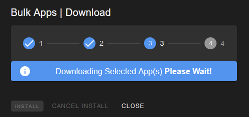
Bulk Installation and Updating of Apps/Services
To update or install multiple apps/services at once, select the check-box next to the desired apps/services to be installed/updated. After selecting all of the desired apps/services, proceed to click the green `Download Apps` button at the top of the table. Once clicked, a `Bulk Apps | Selected Apps` pop-up will appear. Confirm all of the desired apps/services are selected and then click the blue `CONTINUE` button. Select the required versions of each software, usually this is the latest version available, and then proceed by clicking the `DOWNLOAD APP` button. Let the process complete, and then click confirm after verifying all required apps/services have been successfully installed by finally clicking the `INSTALL` button.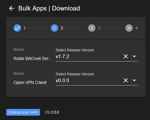
Uninstalling or Deleting Apps/Services
Apps/Services can be uninstalled and deleted using the red `DELETE` bin icon (under the `Actions` column) on the row of the app/service wishing to be removed. Once the red `DELETE` bin icon is clicked, a confirmation window confirming deletion pops-up. Click `YES` to delete the app/service. Wait for the process to complete, and the page will automatically refresh. Ensure the app/service has been successfully removed.
Config File Actions
The config file is a text file (usually in JSON format) that is used to configure apps and services ( Wires, BACnet Master and BACnet Server, Modbus Server and point server). For details on the required content of a config file, please contact Nube-iO Support.
Editing Config File
The config file can be edited by clicking the blue pencil icon on the row of the app/service required to be changed, under the `Config File` heading of the table. From the subsequent pop-up, the existing configuration can be changed/altered. Depending on the type of app/service, the pop-up will display either a simple editor or an advanced code/json editor. Click `Save` to update the config file, or `Cancel` to abandon changes and leave the config file unchanged.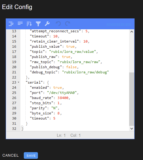
Downloading Config File
The config file can be downloaded by clicking the download icon on the row of the app/service needing to be downloaded. Depending on the app/service, the file downloaded will vary, with usual extensions being that of .txt, .ovpn, .env, .xlxs, and .json. Save the file to the required location on the computer.
Delete Config File
Deleting the config file can be completed by clicking the red bin icon on the required app/service row. It is important to note that this will delete all of the app's/service's configured settings. It is advised to download the config file first before deleting, just in case reverting to the previous config is required.
Database Actions
Rubix apps/services utilise a database to store required information and configurations. These databases can be either downloaded or deleted by using the action buttons in the `Database` column. Deleting an app/service database (and then restarting the app/service) will reset the app to blank slate (as if it was newly installed).
Downloading Database
Databases can be downloaded by clicking the download button under the table heading `Database` on the required app/service row. The database can be saved to a location on the local computer or wherever desired.
Deleting Database
Databases can be deleted by clicking the red bin icon, under the `Database` column on the required app/service row. This will delete the database and configuration of the app/service, so it is vital to have backups of the database as there is no recovery. Click `CONFIRM` on the pop-up to confirm deletion of the database.
Connectivity / Connection Management
LoRa Network
Nube-iO controllers are equipped with LoRa (RAW) radio cards, to act as Wireless LoRa (RAW) Gateways to receive data from Wireless LoRa Sensors using the Rubix Platform.Configuring LoRa Networks
Navigate to `SERIAL NETWORKS` SettingsSelect 'Driver > LoRa Network' from the Rubix Platform Sidebar; Next select the `SERIAL NETWORKS` tab. Here you will see the LoRa Network settings.Configure `SERIAL NETWORKS` SettingsIt is essential that the `SERIAL NETWORKS` settings are correctly configured for the LoRa Gateway to operate. The `SERIAL NETWORKS` settings should be configured with values as follows:Port: /data/socat/loRa1 (for a Rubix Compute 5)Baud Rate: 38400Stop Bits: 1Parity: NByte Size: 8Timeout: 5The `SERIAL NETWORKS` settings should match the image below:RC5 LoRa Settings
Adding and editing Droplet sensors on the Rubix Platform
To receive data from Nube-iO Droplet Sensors they must be added to Rubix Platform. To begin ensure that your Droplet sensors have been configured correctly; see Droplet Installation and Setup. Droplet Sensors operate using LoRa wireless communication, and therefore must be added to the LoRa Network in Rubix Platform.
Adding a Droplet
- Navigate to LoRa Network: Select 'Driver > LoRa' from the Rubix Platform Sidebar; Next select the 'LORA NETWORK' Tab. Here you will see a blank table, or previously added LoRa devices.
- Add the Sensor: Click the `CREATE +` Action Button. An `Edit` popup will appear. For a Droplet Sensor the `name`, `sensor id`, `sensor type`, and `sensor model` fields must be filled in. See below for a description of each field. The `Enable` tickbox must also be checked. When this information is compelte click the `SAVE` button to add the Sensor.
`Edit` Field Descriptions:
- Name - This is the name of the sensor.
- Sensor ID - This is the 8 digit alphanumeric Device ID that is printed on each Droplet Sensor. Example Sensor ID: `A25C8FF3`
- Enable - This is a tickbox that should be checked in order to enable the sensor once added.
- Sensor Type - Select `DROPLET` from the dropdown.
- Sensor Model - Select the DROPLET model that matches the Droplet hardware model.
- AI 1 Config - Not used for Droplet sensors.
- AI 2 Config - Not used for Droplet sensors.
- AI 3 Config - Not used for Droplet sensors.
- Description - Information can be added in the Description for future reference.
Testing Added Droplet Sensors
- Navigate to the LoRa Points for the Sensor - Click the 'Refresh' Action Button to see the updated list of sensors in the table. Clicking the Name of a sensor in the table will open the LoRa Points page for the selected sensor. Check the Breadcrumb Path to ensure that the correct sensor has been selected. The table on the `LoRa Points` page will show the points for the selected sensor, and information about each sensor point.
- Wait for a Sensor Data Push - Droplet sensors push their data at the hardware configured time period. Wait for at least this Push Rate time, or push the Reset Button within the Droplet Sensor to manually trigger a Data Push.
- Check for Values and Timestamps - In the `LoRa Points` page look at the `Value` column; If a Data Push has been received there should be values for all points in this column. Another way to check that data is being received is to look at the `Last Value Change Timestamp` column; If a Data Push is received the timestamp will be updated.
Note 1: Use the `Refresh` Action Button to refresh the table data.Note 2: `Last Value Change Timestamp` will only update if the point value has changed by at least the `COV Threshold` amount. With the temperature point `COV Threshold` set to 0.01 there is likely to be a value change on each push; so look at the temperature point `Last Value Change Timestamp` if others have not changed.
Adding and editing Micro Edge sensors on the Rubix Platform
To receive data from MicroEdge sensors they must be added to Rubix Platform. To begin, ensure that your MicroEdge sensors have been configured correctly.
Adding a MicroEdge
- Navigate to LoRa Network: Select 'Driver > LoRa' from the Rubix Platform Sidebar; Next select the 'LORA NETWORK' Tab. Here you will see a blank table, or previously added LoRa devices.
- Add the Sensor: Click the `CREATE +` Action Button. An `Edit` popup will appear. For a MicroEdge Sensor the `name`, `sensor id`, `sensor type`, `sensor model`, `AI 1 Config`, `AI 2 Config`, and `AI 3 Config` fields must be filled in. See below for a description of each field. The `Enable` tickbox must also be checked. When this information is compelte click the `SAVE` button to add the Sensor.
`Edit` Field Descriptions:
- Name - This is the name of the sensor.
- Sensor ID - This is the 8 digit alphanumeric Device ID that is printed on each MicroEdge Sensor. Example Sensor ID: `A25C8FF3`
- Enable - This is a tickbox that should be checked in order to enable the sensor once added.
- Sensor Type - Select `MICRO_EDGE` from the dropdown.
- Sensor Model - Select `MICRO_EDGE` from the dropdown.
- AI 1 Config - This is specific to the MircoEdge sensor on Analog Input 1 (AI1), select the required analog input from the dropdown (`TEMP`, `VOLTAGE`, `DIGITAL`, or `RAW`)
- AI 2 Config - This is specific to the MircoEdge sensor on Analog Input 2 (AI1), select the required analog input from the dropdown (`TEMP`, `VOLTAGE`, `DIGITAL`, or `RAW`)
- AI 3 Config - This is specific to the MircoEdge sensor on Analog Input 3 (AI1), select the required analog input from the dropdown (`TEMP`, `VOLTAGE`, `DIGITAL`, or `RAW`)
- Description - Information can be added in the Description for future reference.
Testing Added MicroEdge Sensors
- Navigate to the LoRa Points for the Sensor - Click the 'Refresh' Action Button to see the updated list of sensors in the table. Clicking the Name of a sensor in the table will open the LoRa Points page for the selected sensor. Check the Breadcrumb Path to ensure that the correct sensor has been selected. The table on the `LoRa Points` page will show the points for the selected sensor, and information about each sensor point.
- Wait for a Sensor Data Push - MicroEdge sensors push their data at the hardware configured time period. Wait for at least this Push Rate time, or push the Reset Button within the MicroEdge Sensor to manually trigger a Data Push.
- Check for Values and Timestamps - In the `LoRa Points` page look at the `Value` column; If a Data Push has been received there should be values for all points in this column. Another way to check that data is being received is to look at the `Last Value Change Timestamp` column; If a Data Push is received the timestamp will be updated.
Mapping LoRa Points to Rubix Points
Creating a Rubix (Generic) Network
First we will create a Rubix (generic) network, this is where the Rubix Points will be created later in the process. If a generic network has not been created already, it must be done before proceeding with mapping points to Rubix.To create a generic network, navigate to Rubix Platform:
- Once on Rubix Platform, and using the Sidebar, click on `Driver > Rubix`.
- On the `Driver > Rubix` page click the green `CREATE+` button.
- On the `Create Network` pop-up that appears, enter a relevant network name. It is recommended to call it something easy to identify for future reference (such as `LoRa`).
- Ensure that the check-boxes of `Enable` and `History Enable` is ticked.
- Click `Save` in the bottom right hand corner to create this network.
Configuring LoRa Point Mapping
The next step to the point mapping process is to use the Point Mapping service to create Rubix (generic) points and link them to the LoRa points. To do this, navigate to the `Config > Point Mapping` page on Rubix Platform. This can be found on the Sidebar of Rubix Platform. If it is non-existent on the Sidebar, see Rubix Platform: Customising the Sidebar to display this option on the Sidebar.
- On the `Config > Point Mapping` page, click the tab `LoRa Points <> Rubix | BACnet Points` in the top right.
- The first field `LoRa Points` is where all the required LoRa devices/points can be selected. Use `Select all` to select all devices, or individual devices and their individual points (such as voltage, rssi, temperature, etc).
- On the section titled `Generic Points` select the required generic network created previously (from the dropdown labelled `Select Existing Generic Network`. If no generic network is available, or the desired network isn't present, see the above section Creating a Rubix (Generic) Network.
- On the section titled `Generic Points` toggle the switch `Auto create new device(s), point(s) and mapping(s)` to the ON position. This will automatically generate devices and points in the Rubix (Generic) Network created previously. The generated points can be seen the moment the switch is toggled on. Change any required points by selecting the editing pencil next to the desired point.
- Click the `ADD` button located on the bottom left of the screen.
- Wait until all of the devices have been added to the port mappings. The time it takes is dependent on how many devices/points are being mapped.
The `Mappings` section will automatically refresh once the devices have been successfully mapped. If however the devices are not shown, or they are showing delayed data, the refresh button can be pressed to force a refresh of the mapping table. This refresh button is located directly next to the blue `Sync` button above the `Mappings` table.Editing or Deleting Existing Points
Existing points can be edited or deleted by using the `Mappings` table on the `LoRa Points <> Rubix | BACnet Points` tab of the `Config > Point Mapping` page.Editing an Existing Point
To edit an existing point, using the search bar or scrolling on the `Mappings` table, click the edit/pencil icon next to the desired point. This will bring up an `Edit Mapping` pop-up in which details of the mapping can be changed.Deleting an Existing Point
Single or multiple points can be deleted at once. To delete single or multiple points, select the check-boxes next to the desired points to be deleted. To select all points, make sure that the table is set to display all points, and then click the checkbox on the table titles. use the After selecting all of the required points that would like to be deleted, click the red `DELETE` button at the top of the `Mappings` table. Confirm the deletion on the pop-up that appears. Additoonally, on individual points, the red trash can icon can be clicked and then confirm the delete on the pop-up.Modbus Network Configuration
Rubix Platform handles the configuration and management of Modbus services. Modbus is an industry-standard communications protocol for communication between industrial devices, and is compatible with Rubix Platform.
It is important to ensure that the Modbus Service is running on Rubix Platform so that communication with the connected Modbus devices can occur.Using the Sidebar, click on the `Apps > Services` option. Once on the `Installed Apps` page, look for a tile called `Modbus`, with the coloured status icon for this service showing the current state. It should be green and labelled `Running`. If it is not `Running`, then ensure that the service `Enable` switch is ON/Green, and then click the `Restart` button . Refresh the page and check the status has become `Running`. If the `Modbus` tile is not visible, then the Modbus service will need to be installed (see the Rubix Platform: Installing and Updating Services)
Once we have confirmed that the Modbus Service is running, the Modbus Service can be accessed via the `Driver > Modbus Master` option in the Sidebar. If the `Driver > Modbus Master` option is not available see Rubix Platform: Customising the Sidebar.
Add/Configure Modbus Networks
Existing Modbus Networks can be edited by clicking the blue pencil icon on the left of the existing Modbus Network. A new Modbus Network can be added by clicking the `CREATE +` button at the top of the screen.
The settings for the networks are as follows:Network name - The network name is the name of the desired network. It is recommended you use the type of modbus communications (eg. LoRa or RS485-1 / RS485-2).Type - TCP this option is for Modbus over Ethernet/Network. RTU this option is for using Modbus over a wired RS485 or wireless LoRa network.Enable - Tick to enable the Modbus Network.Delay between points (ms) - This is the minimum time (in milliseconds) between the individual Modbus poll requests.Timeout - This is the time (in seconds) that the Modbus Service will wait for a response from the Modbus Device before moving on to the next Modbus poll.RTU parity - (RTU ONLY) Parity setting must match for all devices on the Modbus Network.RTU speed - (RTU ONLY) This is the BAUD RATE setting. Baud Rate setting must match for all devices on the Modbus Network.RTU stopbits - (RTU ONLY) Stop Bit setting must match for all devices on the Modbus Network.RTU bytesize - (RTU ONLY) Byte Size setting must match for all devices on the Modbus Network.RTU port - (RTU ONLY) Select from the dropdown the serial port that is used for the Modbus Network. For RS485-1/RS485-2 ports, use `/dev/tty/RS485-1` / `/dev/tty/RS485-2` RTU ports. respectively. For wireless LoRa Network, use `/dev/tty/XBEE-2`.IP - (TCP ONLY) This is the IP Address of the Modbus TCP Device (Gateway) that you are communicating with.Port - (TCP ONLY) This is the IP Address of the Modbus TCP Device (Gateway) that you are communicating with.Wired RS485 Network (RS485-1 and/or RS485-2)
There should be a Modbus Network for Modbus Devices connecting via wired (RS485) to this Rubix device. We recommend naming this network `RS485-1` or `RS485-2` depending on which port on the Rubix device is used, these correspond to the labelled ports on the device. The settings should match the settings shown below. See above for an explanation of what each of these settings pertain to.Network name - RS485-1 or RS485-2 (depending on the port used)Type - RTUEnable - TickedDelay between points (ms) - 60Timeout - 1RTU speed - 38400RTU stopbits - 1RTU bytesize - 8RTU port - /dev/ttyRS485-1 or /dev/ttyRS485-1 (depending on the port used)Wireless LoRa Network
To add a Modbus Wireless Network via wireless (LoRa) to the Rubix Platform, use the following settings below:Network name - LoRaType - RTUEnable - TickedDelay between points (ms) - 6000Timeout - 5RTU parity - noneRTU speed - 38400RTU stopbits - 1RTU bytesize - 8RTU port - /data/socat/serialBridge1 (For an Rubix Compute 5)
Modbus TCP (Ethernet) Network Settings
The settings below will show you how to create a Modbus Network for Modbus Devices connecting via Ethernet/Networked to this Rubix device.Network name - Name related to the Modbus Device/Gateway you are connecting to.Type - TCPEnable - TickedDelay between points (ms) - 60Timeout - 1IP - IP address of the Device/Gateway you are connecting toPort - Modbus Port of the Device/Gateway you are connecting to (this is a number)
Modbus Device Configuration
Modbus Devices can be added to existing Modbus Networks. Click the previously created Modbus Network for the type of connection for the device to be added, this will bring you to the Modbus Devices page.
Add & Configure Modbus Devices
- Existing Modbus Devices can be edited by clicking the blue pencil icon on the left of the existing Modbus Network.
- A new Modbus Devices can be added by clicking the `CREATE +` button at the top of the screen.
The settings for the Device are as follows:Device Name - The name of the device, use a naming convention to easily identify the specific device.Enable - If ticked, this enables the point.Supports Multiple r/w - This can be ticked if the Modbus Device supports reading/writing multiple registers at once. See your Modbus Device manual to confirm.Zero Mode - This can be ticked if your Modbus Device has registers starting at 0 instead of 1 (Ex. Holding Register 1 = address 400000, use Zero Mode;Holding Register 1 = address 40001 don't use Zero Mode).Ping Point - This specifies the point to be used as a Ping Point to check the device is online. Formatted as Function-Code:Address:Length (default value is 1:1:1).Address - The address of the point in relation to the Modbus NetworkOnce the settings are entered and `SAVE` has been clicked in the bottom right, wait a few minutes for the Modbus communication to be established. Once there is a connection with the controller, the Modbus Device will become a black row (instead of orange).
Modbus Point Configuration
Modbus Points can be added to existing Modbus Devices. Click the previously created Modbus Device, this will bring you to the Modbus Points page for that Device.
Add & Configure Modbus Point
Existing Modbus Points can be edited by clicking the blue pencil icon on the left of the existing Modbus Device. A new Modbus Point can be added by clicking the `CREATE +` button at the top of the screen.
The settings for the point are as follows:Point name - The name of the point, use a naming convention to easily identify the specific point.Enable - If ticked, this enables the point.Writeable - If ticked, this enables values to be written to the modbus register for this point.Write Value Once - If ticked, this enables the point's values to be only written once on COV.COV Threshold - The amount the Modbus read value must change by in order to update the Point Present Value. For most Modbus Points this should remain at 0 (default).Function Code: This will automatically change depending on the other variables and does not need to be set.
- READ_COILS - Read only for coil type modbus points.
- READ_DISCRETE_INPUTS - Read only for discrete input coil type modbus points.
- READ_HOLDING_REGISTERS - Read only for holding register type modbus points.
- READ_INPUT_REGISTERS - Read only for input register type modbus points.
- WRITE_COIL/WRITE_COILS - Read/Write for coil type modbus points. Select WRITE_COIL or WRITE_COILS for writable coil registers, these options are interchangeable.
- WRITE_REGISTER/WRITE_REGISTERS - Read/Write only for holding register type modbus points. Select WRITE_REGISTER or WRITE_REGISTERS for writable holding registers, these options are interchangeable.
Data Type - The type of data variables expected.Data Endian - Refer to the Modbus Device manual to determine the correct data endian function.Register - The modbus register of the point.Register Length - This does not need to be set. It will be set automatically based on the Data Type.Point Round/Math SectionValue - This does not need to be set.Value Round - Rounding of the modbus read value to the specified number of decimal places.Math Operation - This is a basic equation (with the original point value as x) that modifies the present value based on the result of the set equation.Value Raw - Leave blank.Fallback Value - This is the value that will be written to the point if the priority array is null for all priorities. This can be left blank.Point Value Scale Section - Setting these properties will cause the raw read value to be scaled based on the values entered. Input -> Scale.input_min - This is the minimum input value to be expected.input_max - This is the maximum input value to be expected.scale_min - This is the minimum desired scale of the point; corresponds to input_min.scale_max - This is the maximum desired scale of the point; corresponds to input_max.After setting all of the desired and correct values in this pop-up, click the `SAVE` button in the bottom right to add this point to the device. Refresh the page and the point should be added. Once data has been read from the point, it will change from orange to grey.
Point Actions
Individual points can be edited, deleted, or written to using the action buttons on the row of each specific point.Editing an Existing Point
Editing an existing point is as simple as clicking the blue pencil icon and entering the required data into the `Edit Point` pop-up. After entering the required edits to be made to the point, click `SAVE` to confirm these changes and apply them to the point.Deleting an Existing Point
Points can be deleted by clicking the red bin icon on the row of the point that is required to be deleted. Upon clicking the red bin icon, a confirmation pop-up appears, click `CANCEL` to cancel the deletion of the point, or click `CONFIRM` to proceed with the deletion of the point.Writing to an Existing Point
Data can be written to existing points by clicking the orange Modbus icon on the row of each specific point required to write. Once clicked, a pop-up will appear of the selected point, with two sections: point write, and point release priority. Enter in the desired values in to each section and click the blue `SEND` button to write this data on each individual item that has been entered. Click the `CLOSE` button when the data has been sent/written.
BACnet Server Configuration
The Rubix compute supports being setup as a BACnet server and has the ability of acting as a BACnet gateway, enabling the controller to sit on any BACnet network and accept commands from BACnet master devices.
The Rubix Compute currently only supports BACnet over IP, not BACnet over MSTPThe Rubix Compute can only act as a BACnet Server OR a BACnet Master. Ensure only one service is running at the same time

The BACnet Server app must be first downloaded in order for the controller to work as an BACnet server.
Using the Sidebar, click on the `Apps > Services` option. Once on the `Installed Apps` page, look for a tile called `Rubix BACnet Server`, with the coloured status icon for this service showing the current state. It should be green and labelled `Running`. If it is not `Running`, then ensure that the service `Enable` switch is ON/Green, and then click the `Restart` button. Refresh the page and check the status has become `Running`. If the `Rubix BACnet Server` tile is not visible, then the service will need to be installed (see the Rubix Platform: Installing and Updating Services).
Once we have confirmed that the BACnet server is running, the service can be accessed via the `Driver > BACnet Server` option in the Sidebar. If this option is not available see Rubix Platform: Customising the Sidebar.
Configuring BACnet Server settings
The BACnet server must be configured correctly in order for the controller to be discovered by a BACnet master device.Steps to configure the BACnet server:
- Set the required IP of the BACnet server. The IP must be a valid IP from either ETH1 or ETH2 or the device
- Change the 'Port', 'BACnet Device ID' and 'Device Name' if required
- Click 'save' and then restart the BACnet-server app, otherwise the settings will not update
In the BACnet server tab, enter the IP of the controller followed by '/' and the network's subnet mask. To work out the subnet mask, use a calculator such as this.In the example below, the controller's IP is 192.168.15.10 and the subnet is 255.255.255.0, which works out to be 24 using the calculator.
BACnet-Server App Config File
The configuration file must also be added by clicking the blue pencil button on the 'Rubix Apps' overview page.Reasons to adjust the config file:
- Using a preset ethenet addr, device-id and device name
- Changing the MQTT broker details for where the data is sent
Download or copy the config file from here. Similar to above, the IP and subnet mask must be changed to match the controller.Restart the BACnet server app in order for the settings to take place.
BACnet-Server Status Page
- The MQTT (Mosquito) service is required if you wish to access the data within Rubix-Wires
- The status icon will change to green if all the settings are correct
Adding a BACnet point
To add a BACnet server point, click the 'Create +' button at the top of the screen in the 'BACnet Server' sidebar.The input settings for the app are as follows:Object Type - AnalogValue, analogOutput, binaryValue, binaryOutputObject Name - Give the point a desired nameAddress - BACnet point address. Each point must have a unique addressUnits - Units of measurement for the BAnet point, can be left blank if unknown or not requiredDescription - Point descriptionRelinquish Default - fallback valueEvent State - Normal, fault, offnormal, highLimit, lowLimit, lifeSafetyAlarm
Point Actions
Individual points can be edited, deleted, or written to using the action buttons on the row of each specific point.
Editing an Existing Point
Editing an existing point is as simple as clicking the blue pencil icon and entering the required data into the `Edit Point` pop-up. After entering the required edits to be made to the point, click `SAVE` to confirm these changes and apply them to the point.
Deleting an Existing Point
Points can be deleted by clicking the red bin icon on the row of the point that is required to be deleted. Upon clicking the red bin icon, a confirmation pop-up appears, click `CANCEL` to cancel the deletion of the point, or click `CONFIRM` to proceed with the deletion of the point.
Writing to an Existing Point
Data can be written to existing points by clicking the orange Modbus icon on the row of each specific point required to write. Once clicked, a pop-up will appear of the selected point, with two sections: point write, and point release priority. Enter in the desired values in to each section and click the blue `SEND` button to write this data on each individual item that has been entered. Click the `CLOSE` button when the data has been sent/written.
Once the BACnet server and points have been set up, the Rubix Compute BACnet points now should be discoverable on a BACnet master device or program, such as a Niagara JACE. The points on the Rubix BACnet server app should match the points on the Master BACnet server.BACnet points can be added to the application by mapping LoRa droplets or Modbus points to BACnet points. For more information on mapping LoRa or Modbus points to BACnet, refer to: Rubix Platform: Mapping Modbus & LoRa points to BACnet Points
Related Articles
Rubix Wires: Overview
Introduction to Rubix Wires Rubix Wires is Nube-iOs browser based logical programming environment. It is a function block flow editor, so there is no coding required to make advanced control and monitoring programs. This type of visual programming ...Rubix Platform: Getting Started Guide
Introduction To Rubix Platform Rubix Platform is the browser based user interface for many of the Nube-iO services. Rubix Platform is the main management tool for configuring Local/Remote Device Settings, Sensor Gateway Connectivity, Data Management, ...Rubix Wires: Navigation
This article explains how to navigate the Rubix Wires browser based logical programming environment. Knowing the names and locations of the common Menus, Buttons, and Panels available in Rubix Wires will help you understand the instructions and ...Rubix Wires: Getting Started Guide
Introduction to Rubix Wires Rubix Wires is Nube-iOs browser based logical programming environment. It is a function block flow editor, so there is no coding required to make advanced control and monitoring programs. This type of visual programming ...Rubix Platform: Navigation
This article explains how to navigate the Rubix Platform browser based user interface. Knowing the names and locations of the common Menus, Buttons, and Panels available in Rubix Platform will help users understand the instructions/descriptions in ...